ANSYS FLUENT is a powerful tool for optimizing the process of design and technological preparation in the field of computational dynamics of liquids and gases. The ANSYS FLUENT software module has a wide range of capabilities for simulating fluid and gas flows for industrial applications, taking into account turbulence, heat transfer, and chemical reactions. FLUENT simulates tasks such as combustion in furnaces, flow within the bubble column, external flow of oil platforms, flow in the circulatory system, convective cooling of the semiconductor assembly, ventilation in rooms, and modeling of industrial wastewater. Specialized models of combustion, aeroacoustics, rotating/fixed calculation areas, and multiphase flows seriously expand the scope of application of the base product. If you want to know how to use ANSYS FLUENT, check out the following sample.
Our example allows even beginners in engineering to achieve good results in their own assignments. It offers a comprehensive solution for students who don’t know how to do their tasks. The samples fully explain how to use ANSYS FLUENT. This example allows a student to deal with his or her assignment much faster and easier, otherwise they can get help with assignment from us. So, read through the guide right now!
How to Work With Ansys Fluent Module
Task: Get basic knowledge of how to work with Ansys Fluent module on example of the problem shown below.
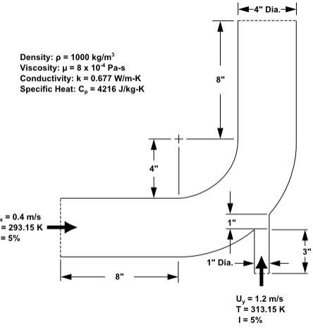
The problem is shown schematically in the figure below. A cold fluid at 293.15 K flows into the pipe through a large inlet and mixes with a warmer fluid at 313.15 K that enters through a smaller inlet located at the elbow. The mixing elbow configuration is encountered in piping systems in power plants and process industries. It is often important to predict the flow field and temperature field in the area of the mixing region in order to properly design the junction.
Solution:
(Part 2)
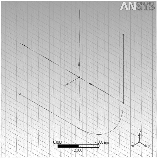
Create the path:
- On the Modeling tab select XYPlane, then click the New Sketch icon and then the Generate button to create a new sketch based on the XYPlane.
- On the Sketching tab, open the Settings toolbox, select Grid, and enable the Show in 2D and the Snap options.
- Set Major Grid Spacing to 1 inch and Minor-Steps per Major to 2.
- In the Draw toolbox, select Line to draw two straight lines on the sketch. For reference, the coordinates of the endpoints of the lines are: (X = −8 inches, Y = − 6 inches), (X = 0 inches, Y = −6 inches) for the horizontal line and (Z = 6 inches, Y = 0 inches), (X = 6 inches, Y = 8 inches) for the vertical line.
- In the Draw toolbox, select Arc by Center and click once on the origin (center of the arc). Now click once on the point X = 6 inches, Y = 0 inches to select one of the end points of the arc. With the mouse unclicked, move the mouse around to the other end point.
Create the pipe:
- Select the Sweep button from the 3D Features toolbar.
- Set the Profile to be Sketch1 by clicking Sketch1 in the Tree Outline and then clicking Apply next to Profile in the Details View at the bottom-left of the screen.
- Set the Path to Sketch2: Click Sketch2 in the Tree Outline, then click the unselected text next to Path in the Details View and click Apply.
- Click the Generate button to create the pipe.
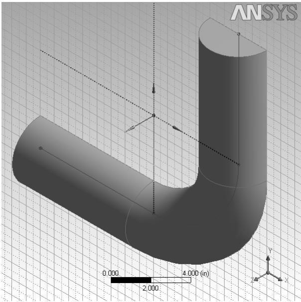
You can use the mouse buttons to change your view of this 3D image.
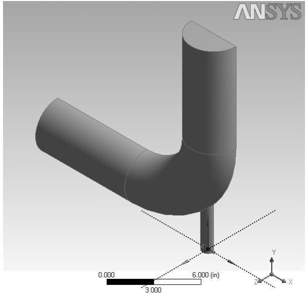
Create the side pipe:
- Create a new plane based on the ZXPlane. As before, first make the ZXPlane active by clicking on it, then click the New Plane icon to create the plane based upon it.
- In the Details View, set Transform 1 (RMB) to Offset Global X, and set the FD1, Value 1 of the offset to 5.5 inches. iii. Set Transform 2 (RMB) to Offset Global Y and the FD2, Value 2 of the offset to -9 inches.
- Click Generate to create the plane.
With the new plane selected in the Tree Outline, click the New Sketch icon. - As with the main pipe, a profile will be created, but with the side pipe, the Extrude operation will be used to create the body of the pipe. On the Sketching tab, open the Draw toolbox and select Arc by Center. You will be drawing a 180° arc that is centered on the origin, with the two ends on the X axis. The radius for this arc will be adjusted later, so you can use any convenient radius for now. Click once on the origin, then once some distance along the X axis in either a positive or a negative direction. With the mouse button unclicked, draw an arc to the opposite side of the origin and click the X axis again.
- To adjust the radius, open the Dimensions toolbox on the Sketching tab and select Radius. Click once on the curve of the arc you have just created, then click once on the radius (anywhere between the arc and the origin). In the Details View under the Dimensions: 1 section, set the radius, R1 to 0.5 inches.
- Next you will close the half-circle with a line that joins the two arc ends. On the Sketching tab, in the Draw toolbox, select Line. Draw a line connecting the open ends of the arc. This closed half-circle will be used as the profile for the extrude operation. ix. Click the Extrude button from the 3D Features toolbar.
- In the Details View, set Geometry to be the new sketch (Sketch3), and set Operation to Add Material.
- Set Direction to Normal and Extent Type to Fixed. Set FD1, Depth (>0) to 4 inches.
- Click Generate to create the side pipe.
Specify the geometry as a fluid body:
- In the Tree Outline, open the 1 Part, 1 Body branch and select Solid.
- In the Details View of the body, change the name of the Body from Solid to Fluid.
- In the Fluid/Solid section, select Fluid.