A joint calculation is performed in the case where it is required to give a quantitative estimate of the degree of curvilinearity of the correlation relation, while determining the coefficient of determination r2 and the point of the empirical line. If you need to do some calculations, our bolted joint calculation example will help you.
Start doing your assignment from reading through our example of bolted joint calculations. After that, you can deal with your task easily. The results will be much better if you decide to use the example. It is necessary to understand the topic in order to complete the assignment successfully, and our sample can help with that. You can also check out other samples presented on our blog, which can help with assignments for different disciplines. Each of the examples is done by an expert in the field. Read through our example to deal with your joint calculations easily.
Joint Calculation
Task description: calculate the bolted joint given in Figure 1.
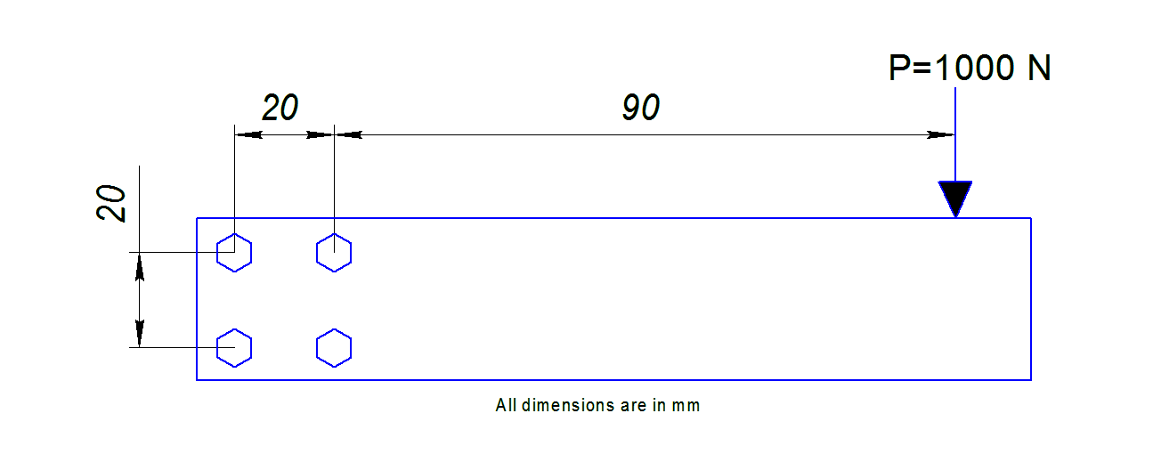 Figure 1 – General View of Beam
Input Data:
Geometry of the bolt joint – see Figure 1;
Applied force – P = 1000 N;
Distance from the applied force to the bolt joint – L = 90 mm;
Number of bolts in the group – n = 4.
All the bolts are of the same type and diameter.
Goal:
Find the load on the individual bolt in the joint.
Solution:
The subject bolt joint is eccentrically loaded. Its free body diagram can be presented as loaded with the vertical force P and a resulting moment M (see Figure 2). The moment is created by the force P eccentricity. Both the load and the moment are applied to the center of gravity of the joint. Since all the bolts are of the same diameter and of the same rigidity (see Input Data section) and the joint pattern is a square, the center of gravity coincides with the center of gravity of the square formed by the bolts (see Figure 2).
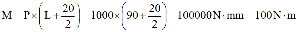
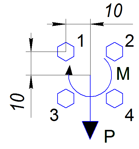
Figure 2 – Free Body Diagram of Bolted Joint
Reactions on a separate bolt consist of two components: R – from the force P, and RM – from the moment M. See Figure 3 for details.
Figure 3 – Joint Reaction Diagram
Since all the bolts have the same mechanical properties the component reaction will be the same.
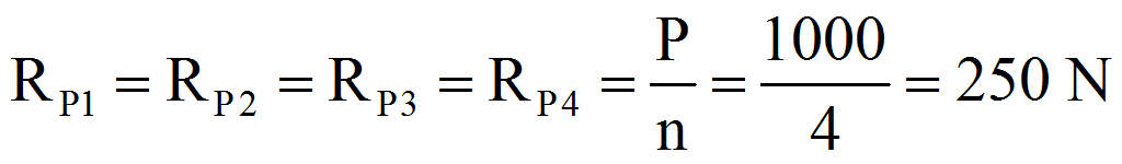
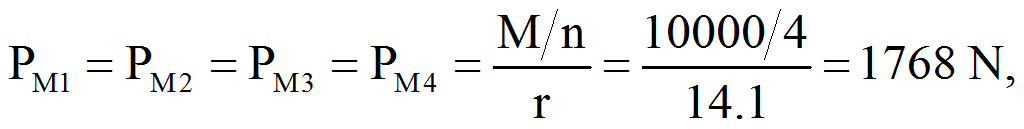
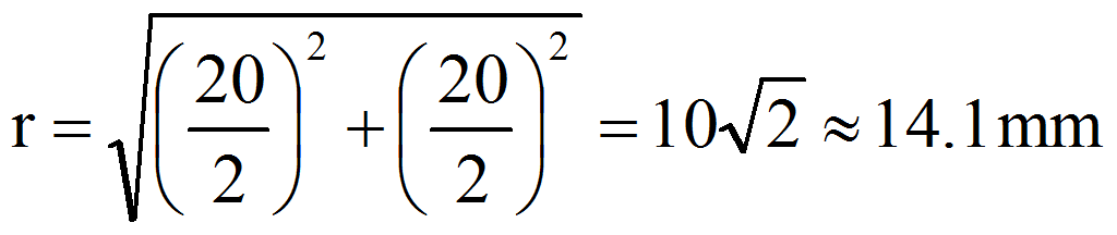
Where r is the distance from the center of gravity of a single bolt to the center of gravity of the group:
Resulting reactions on each bolt:
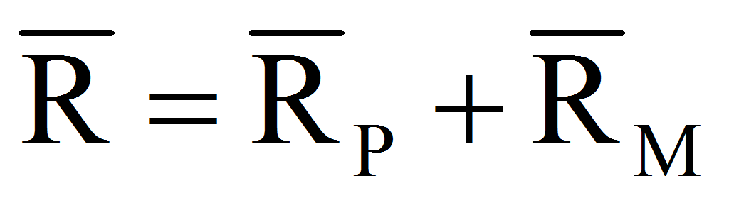
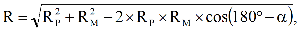
Where α is an angle between RP and RM vectors:
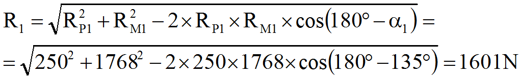
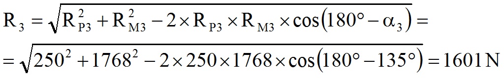
α1 = α3 = 135º;
α2 = α4 = 45º.
Resulting reactions:

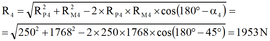
Conclusion:
The most loaded bolts are # 2 and 4 (1953 N).