Simulation is a mathematical technique for emulating circuit behavior. Simulation helps to define many properties of the circuit without assembling the circuit or using real devices. Nowadays, a lot of software is designed to ease the work of the engineer. Today we want to introduce you to the program of the company National Instruments – NI Multisim. In this article, we’ll look at the simplest examples of modeling electrical circuits using Multisim. This program will be useful both for students that need to solve problems in electrical engineering and electronics, and for teachers for scientific activities. While the interface of the program is quite simple, you will need some time to understand how to use it to the fullest. To help you, we have created Multisim examples that show a quick functionality overview.
You can find many Multisim examples on our blog, as well as receieve help with your assignment. Each sample has a variety of screenshots and descriptions of actions that you need to complete the task successfully. Check out the sample below right away!
Multisim Software Quick Functionality Overview. Part 1
Task: Multisim software quick functionality overview with examples (Part 1).
Solution:
First start the Multisim program. After program launch you will see the following window:
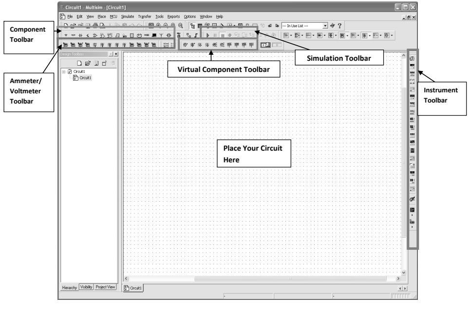 Open / Create Schematic
A blank schematic named Circuit 1 is automatically created. To create a new schematic, click on File → New → Schematic Capture. To save the schematic click on File → Save As. To open an existing file, click on File → Open in the toolbar.
Place Components
To place components, click on Place → Components. On the Select Component window, click on Group to select the components needed for the circuit. Click OK to place the component on the schematic.
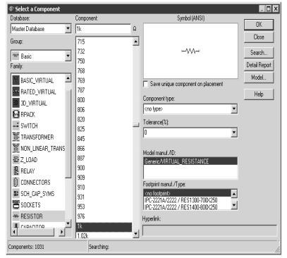 Figure 1: Select Resistor
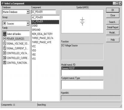 Figure 2: Select DC voltage
Virtual Components
Components can also be placed on the circuit using virtual components. Click on View → Toolbars and select the toolbar needed for the circuit.
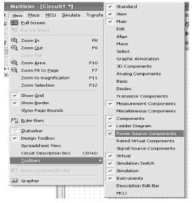 Figure 4: Virtual Components
Rotate Components
To rotate the components right click on the resistor to flip the component 90 clockwise (Ctrl +R) and 90 counterclockwise (Ctrl + Shift + R).
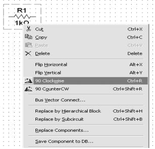 Figure 5: Rotate Components
Place Wire / Connect Components
To connect resistors, click on Place/Wire, and drag and place the wire. Components can also be connected by clicking the mouse over the terminal edge of one component and dragging to the edge of another component.
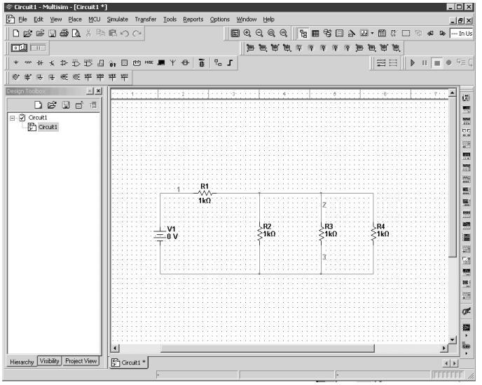 Figure 6: Place / Wire